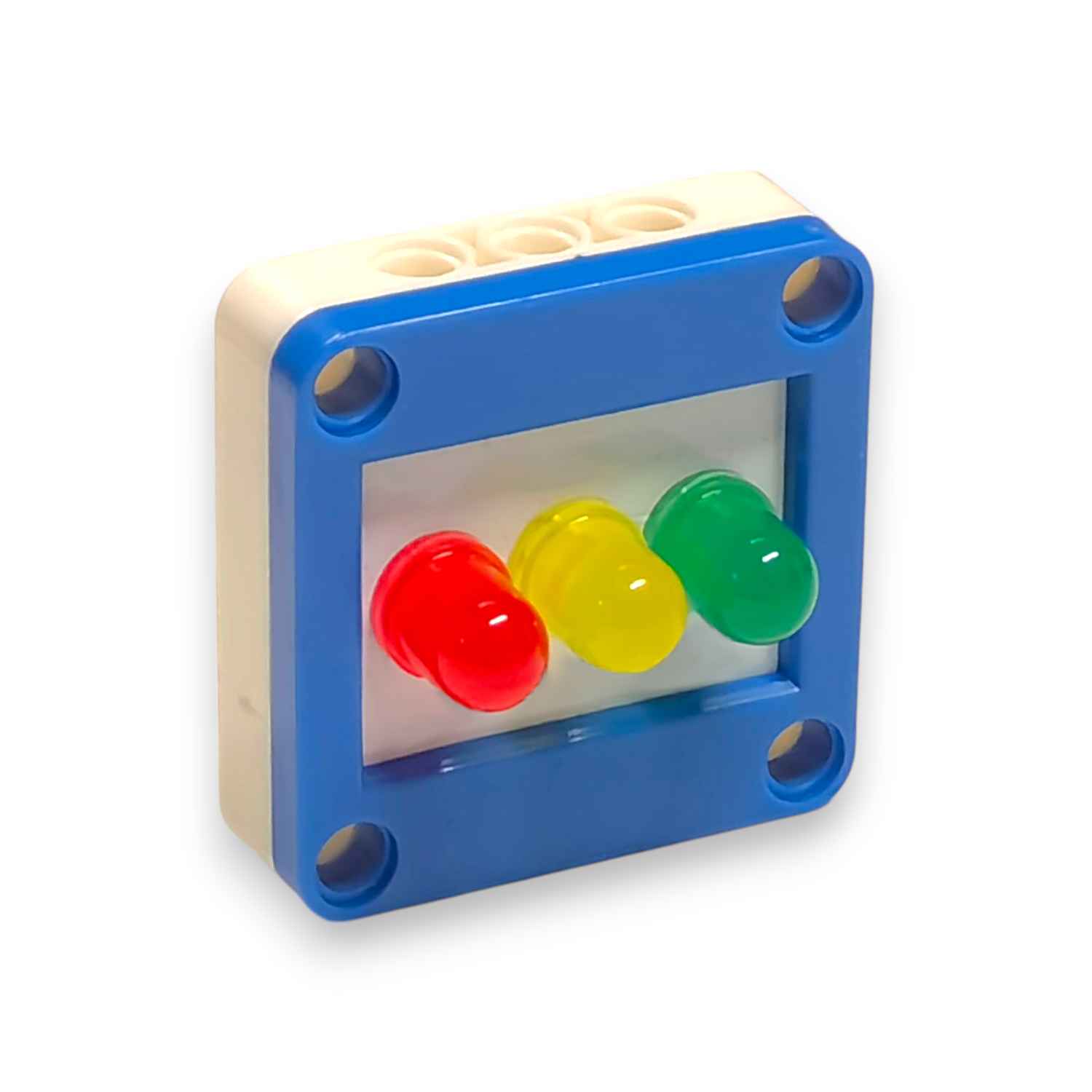
2.10 Traffic Light Module
The Traffic Light Module is used to visually signal different statuses or actions through red, yellow (amber), and green lights. It mimics the operation of traditional traffic lights and is useful in both educational projects and real-world robotics or automation systems.

This module typically consists of:
- Red LED – to indicate "Stop" or "Danger"
- Yellow/Amber LED – to indicate "Caution" or "Wait"
- Green LED – to indicate "Go" or "Safe"
Example Applications:
- Simulating traffic light behavior in smart city or road-safety projects
- Indicating robot states (e.g., idle, warning, active)
- Teaching basic electronics and programming concepts
2.10.1 Example Code for the Traffic Light Module
- Choose a port with two pins such as
P14/P13orP1/P0to plug the traffic light module. This example usesP1/P0. - Select the corresponding pins from the traffic light module functions in Mind+ to match
P1andP0. - Forever Loop: The blocks illustrate a forever loop, meaning the actions inside will repeat indefinitely.
- Initialize: The code starts by setting the traffic light module's
P1pin to GREEN (LED-GREEN ON). - Green Light: The traffic light stays green for 10 seconds.
- Yellow Light: After 10 seconds, the green light turns off, and the
P0pin is set to YELLOW (LED-YELLOW ON) for 2 seconds. - Red Light: After 2 seconds, the yellow light turns off, and the
P1pin is set to RED (LED-RED ON) for 7 seconds. - Loop: The sequence then repeats, going back to the green light.

Figure 3.1.1: Traffic Light Logic in Mind+
