Why Classroom Robot Gearboxes Strip When Learners Push Them by Hand
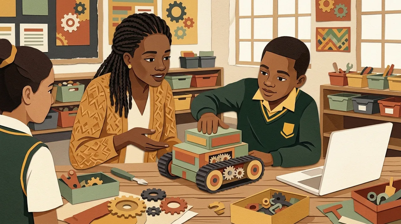
Pushing a stationary robot forces its reduction gears to run backwards at a massive mechanical disadvantage, concentrating shear torque onto tiny plastic teeth until they strip.
When a learner grabs a two-wheeled robot and pushes it across a desk like a toy car, they are backdriving the drivetrain. Inside the gearbox, that hand movement forces a high-ratio geartrain to run backwards, requiring the tiny, slow-turning output shaft to accelerate a motor armature up to thousands of revolutions per minute almost instantaneously. The mechanical advantage reverses, friction compounds across every gear mesh, and the shear force easily exceeds the yield strength of small plastic teeth. The sickening crunch or buzzing click that follows is the sound of those teeth shearing clean off the gear hub.
The Mechanics of Backdriving: Torque in Reverse
In standard operation, a small DC motor spins at high speed with very low torque—typically between 6,000 and 12,000 RPM. Because a robot wheel cannot use that rotational speed directly, engineers place a gearbox between the motor and the axle. A common reduction ratio for classroom platforms like yellow TT motors, micro metal gearmotors, or integrated smart servos ranges from 48:1 to over 120:1.
In the forward direction, this arrangement is forgiving. The high-speed motor pinion drives a larger gear, which drives a smaller pinion on a compound gear, stepping down the speed and multiplying output torque at every stage. But when a child shoves the robot by hand, the power flow flips:
- Speed Multiplication: The wheel axle becomes the input. To move the robot forward at a brisk classroom shove of 0.5 metres per second, the gearbox must force the motor shaft to spin from zero to over 4,000 RPM in a fraction of a second.
- Friction and Inertia Resistance: The motor has rotational inertia and magnetic detent torque (the resistance felt as the magnets pull on the iron core). In reverse, the force required to overcome that motor detent is multiplied by the gear ratio.
- Declining Backdrive Efficiency: Every spur gear mesh loses energy to sliding and rolling friction. While forward mechanical efficiency might sit around 70% to 80% across three or four stages, backdriving efficiency drops steeply. At ratios above 50:1, the internal friction of the gear teeth often approaches a self-locking state.
When the wheels are forced to turn faster than the geartrain can accelerate the motor armature, the mechanical energy has nowhere to go. It concentrates entirely as bending and shear stress on the weakest mechanical link in the gear train.
Why Plastic Teeth Fail First
Classroom robotics kits rely on injection-moulded engineering plastics, usually polyoxymethylene (POM, commonly known as acetal or Delrin) or nylon. These materials are chosen for good reason: they are light, self-lubricating, quiet, and inexpensive to produce in volume. Under normal motor-driven loads, they easily handle the operating torque of an educational robot.
However, plastic gear teeth fail rapidly under three specific conditions common to backdriving:
| Failure Factor | What Happens Mechanically | Classroom Consequence |
|---|---|---|
| Compound Gear Staging | The smallest intermediate gear pinions bear the highest mechanical disadvantage during backdrive. | Failure is rarely on the output axle gear; it almost always strips the tiny 8-to-12-tooth pinion on the secondary cluster shaft. |
| Impact Shock Loading | A sudden shove applies peak torque in milliseconds, bypassing the material's elastic deformation window. | Plastic teeth shear clean off at the root instead of flexing and recovering. |
| Shaft Deflection | Under heavy radial loads from a hand pushing down and forward, thin steel or plastic axle pins flex. | Gear centres push apart, reducing tooth engagement depth from full face contact to fragile tooth tips, which immediately snap. |
If a motor gearbox requires 0.05 Newton-metres to turn forward, backdriving a 90:1 box with compound friction can demand several Newton-metres at the wheel rim. A primary school learner can exert 30 to 50 Newtons of lateral force without trying. The plastic teeth stand no chance.
Mechanical Defences for the Classroom Fleet
Telling forty Grade 6 learners to "be gentle" will not protect your hardware. A resilient classroom fleet requires mechanical safeguards built directly into the chassis design.
1. Mechanical Slip Clutches
If you build with modular systems like LEGO Education kits, always route drive torque through a slip gear (such as the standard 24-tooth white clutch gear) rather than driving wheels directly from the hub axle. These gears use internal spring-loaded detents that slip at approximately 2.5 to 3 N·cm of torque. When a learner pushes the chassis along the floor, the clutch slips with a harmless clicking sound, protecting the internal geartrain of the motor.
2. Indirect Belt and Pulley Reduction
For custom 3D-printed or laser-cut robots, placing a simple silicone O-ring or GT2 timing belt between the motor gearbox output and the wheel axle provides an effective mechanical fuse. If the wheel is forced, the rubber belt slips on the plastic pulley flange long before the torque can shock the motor's internal spur gears.
3. Sacrificial External Gearing
Never mount drive wheels directly to internal motor shafts if replacements are expensive or time-consuming to service. Using a 1:1 external gear pair between the motor shaft and the wheel axle allows you to use cheap, readily accessible external gears. If excessive force is applied, the external gears strip where they can be replaced in two minutes with a screwdriver, rather than requiring the teardown of a sealed motor housing.
Operational Habits That Save Your Budget
Mechanical design solves half the problem; classroom workflow handles the rest. In typical South African computer rooms—where a single laptop trolley serves hundreds of learners a week and lessons run on tight 45-minute periods—routine motor maintenance can derail an entire term's schedule.
- Introduce Bench Stands: Provide each workstation with two wooden offcuts or a small 3D-printed U-block to prop the robot's drive wheels off the desk during code downloads and testing. Learners often push running robots down onto the table surface to arrest movement when debugging loops, stripping gears under live power.
- The "Two-Hand Lift" Rule: Establish a clear lab rule from day one: robots travel through the air, never along the desk surface. If a machine needs to be relocated to a test arena or starting tile, learners must carry it.
- Standardise and Stock Wear Parts: Accept that budget spur gearboxes (like standard yellow TT motors) are consumable components. Rather than attempting to glue stripped internal acetal pinions—which never holds—keep pre-tested replacement drive modules on hand. If your school runs custom builds or needs to replenish stripped classroom mechanisms, you can source compatible drive hardware through the Sheen Robotics store to keep workstations operational without replacing entire kits.
- Audit Fleet Friction: When older robots begin pulling to one side, teachers often assume the code or battery is failing. In reality, hair and carpet fibres wrapped around the wheel axle create constant drag, raising internal gearbox temperatures and softening plastic teeth under normal drive loads. Inspect and clear axles termly.
For schools managing large shared robotics labs where ongoing hardware maintenance and motor failures consume teacher prep time, our technicians help maintain and refurbish school hardware inventories through Sheen Robotics school services. Designing out single points of mechanical failure preserves your budget and keeps learners focused on writing code rather than listening to stripped gears spin in place.