
Why Your ESP32 Temperature Sensor Reads 4°C Too High
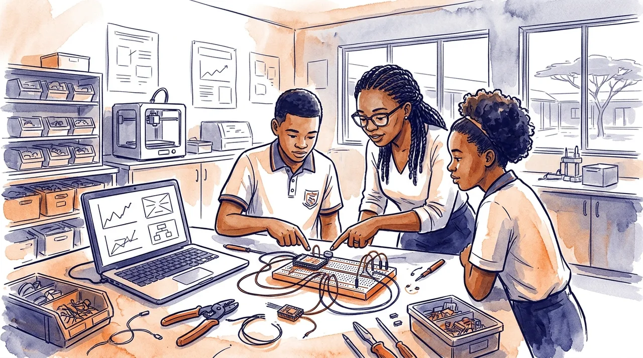
Your sensor is not broken: linear regulators and Wi-Fi transmission bursts dump heat straight into breadboard tracks and enclosures. Here is how to fix thermal creep without fudging calibration code.
Your temperature sensor is almost certainly working exactly as manufactured. The issue is that it is not measuring your classroom's ambient air; it is measuring the thermal microclimate generated by the ESP32 sitting next to it. When a DHT11, DHT22, or BME280 module sits plugged into the same breadboard, custom PCB, or 3D-printed enclosure as an ESP32 development board, onboard heat dissipation consistently skews temperature readings upward by 2°C to 5°C, while depressing relative humidity readings by 10% to 20%.
In classroom robotics and IoT projects, the instinct is often to write a quick software patch: subtracting four degrees from the raw float value. That is a bad engineering habit to teach learners. The thermal offset is dynamic, not linear. It shifts depending on Wi-Fi transmission duty cycles, ambient room ventilation, and whether the microcontroller is actively polling sensors or idling.
The Two Culprits: Linear Regulators and Wi-Fi Transients
An ESP32 development board (such as the standard 30-pin or 38-pin NodeMCU-style boards common in South African schools) is powered via a 5V USB connection. However, the ESP32 system-on-chip (SoC) runs at 3.3V. The voltage drop between the 5V rail and the 3.3V rail is absorbed by an onboard low-dropout linear regulator (LDO), typically an AMS1117 or similar chip.
Linear regulators step down voltage by shedding excess energy as heat. The arithmetic is straightforward: dropping 5.0V to 3.3V leaves a 1.7V difference. When an ESP32 runs its dual Tensilica cores with the Wi-Fi modem enabled, it draws an average current of 80mA to 130mA, with transient current spikes reaching 250mA to 400mA during RF transmission bursts. That means the tiny regulator on your board is continuously dissipating between 140mW and 220mW of pure thermal energy directly into the PCB copper planes.
Simultaneously, the ESP32 SoC itself runs warm. The internal RF power amplifier running 2.4 GHz 802.11b/g/n generates localized heat inside the metal shielding can. If your sensor sits within two or three centimetres of that metal can or the LDO, it operates inside that localized heat pocket.
How Heat Migrates: Conduction and Enclosure Trapping
Heat reaches your sensor through three primary pathways in a classroom build:
- Copper Breadboard Rails: Breadboards are plastic on the outside, but inside they rely on parallel spring-metal tie-strips. When the ESP32 power and ground pins heat up, that thermal energy conducts directly along the metallic strips to neighbouring pins where your sensor breakout is plugged in.
- MEMS Self-Heating: The Bosch BME280 is a microscopic MEMS (micro-electro-mechanical system) sensor. If learners configure it in continuous 'Normal' mode with high oversampling rates, reading it continuously in an infinite Arduino loop, the internal electronics of the sensor package self-heat.
- Stagnant Enclosure Air: When learners house an IoT weather station in a compact 3D-printed case or ABS project box to protect it from classroom knocks, convection stops. The LDO acts like a miniature 200mW space heater inside a sealed box. Within ten minutes, the air inside the enclosure rises well above the ambient temperature of the room.
Classroom Fixes That Work
Rather than patching the firmware with an arbitrary subtraction, use the problem as a practical lesson in thermal design and firmware power management.
| Intervention | Mechanism | Typical Temperature Reduction |
|---|---|---|
| Physical Standoff (10–15 cm jumper leads) | Eliminates board conduction and separates air volumes | 2.5°C to 4.0°C |
| Deep Sleep + Read-Before-Radio Firmware | Cuts LDO current draw and avoids RF heating spikes | 1.5°C to 3.0°C |
| BME280 Forced Mode (Low Sampling Rate) | Prevents internal MEMS self-heating | 0.5°C to 1.0°C |
| Vented Case with Thermal Baffle | Separates radio chamber from sensor intake chamber | 2.0°C to 3.5°C |
1. Physical Separation (The Thermal Standoff)
The single most effective fix is physical distance. Move the DHT22 or BME280 off the microcontroller breadboard entirely. Connecting the sensor via a 10 cm or 15 cm ribbon cable or mounting it on a dedicated thermal standoff immediately decouples the sensor from the PCB's thermal conduction. Furthermore, because warm air rises, always mount the sensor below or alongside the ESP32, never directly above it.
2. Change the Firmware Routine: Read First, Transmit Later
Most novice IoT code follows this sequence: connect to Wi-Fi, establish an MQTT or HTTP link, read the sensor, send the packet, delay for two seconds, repeat. By keeping Wi-Fi active full-time, the board never cools down.
Instead, restructure the routine to use deep sleep, particularly for data logging stations:
- Wake the ESP32 from deep sleep (Wi-Fi radio remains powered off).
- Read the temperature and humidity sensor immediately while the board is cold.
- Initialize the Wi-Fi radio, connect to the school network, transmit the data payload, and instantly shut the radio down.
- Put the ESP32 back into deep sleep for 60 to 300 seconds.
In deep sleep, current draw plummets from ~100mA to microamps on bare modules (or 1–3mA on dev boards with passive USB bridges). The LDO cools down completely, and readings reflect ambient air rather than silicon heat dissipation.
3. Configure Sensors for Low-Power Modes
If you are using the BME280 via libraries such as Adafruit's BME280 library, do not leave it in continuous sampling mode. Switch the sensor to 'Forced Mode'. In Forced Mode, the sensor sleeps, takes a single measurement on demand, returns the data, and automatically drops back to sleep. For classroom ambient monitoring, one reading every 30 to 60 seconds is more than sufficient.
Teaching Good Engineering Practice
When learners observe their weather station reporting 26°C while the wall thermometer clearly reads 22°C, it is tempting to dismiss it as cheap component variance. It rarely is. Testing the system with an infrared thermometer quickly shows the ESP32 SoC running at 35°C or higher on a warm afternoon.
Teaching learners to diagnose the physical heat source, measure the voltage drop across the regulator, and redesign their physical layouts builds real engineering competence. If your school is deploying connected telemetry nodes across classrooms or agricultural tunnels, exploring standardized sensor mounts and low-power IoT architectures through Sheen IoT learning modules provides a structured way to implement these hardware best practices without reinventing the circuit from scratch.